

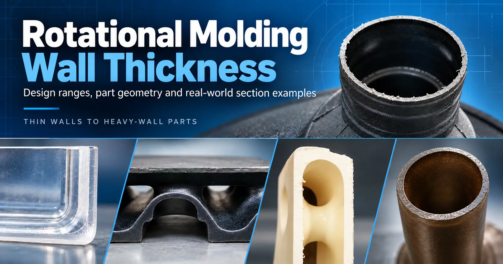
Rotational Molding Wall Thickness: Design Guidelines, Limits & Best Practices
How Part Geometry, Materials, Heat and Processing Affect Wall Thickness in Rotomolded Parts
By RotationalMolding.com Editorial Team
Published October 29, 2026
Wall thickness is one of the most important considerations when designing a rotationally molded plastic part. It affects structural performance, part weight, material usage, molding cycle time, dimensional behavior and ultimately the cost of the finished product.
But rotational molding wall thickness is also frequently misunderstood.
A specification calling for a 0.250-inch (6.35 mm) wall does not mean that every point on the finished part will measure exactly 0.250 inch. Unlike many machining or fabrication processes, rotational molding produces a hollow plastic part by gradually building material against the heated interior surface of a rotating mold. The internal surface of the finished part is essentially free-formed.
As a result, successful rotational molding design requires understanding the difference between nominal wall thickness, minimum wall thickness and the natural variation that occurs throughout a molded part.
At The Granger Plastics Company, wall thickness is considered together with part geometry, mold construction, resin selection, heat transfer, rotation, cooling and the intended use of the finished product.
What Is Nominal Wall Thickness in Rotational Molding?
Nominal wall thickness is the target or average wall thickness around the primary wall sections of a rotationally molded part.
For example, a product may be designed around a nominal wall thickness of 0.250 inch (6.35 mm), or a customer specification may call for a 6 mm nominal wall, which is approximately 0.236 inch.
The word nominal is important.
It describes the intended general wall section rather than guaranteeing that every location on a complex molded part will have exactly the same measurement.
Wall thickness variation is an inherent characteristic of the rotational molding process. The amount of variation depends on factors including part size, geometry, mold construction, material and processing conditions. Tighter wall-thickness control may be achievable through tooling and process development, but increasingly tight tolerances can add manufacturing complexity and cost.
For applications where structural performance depends upon a particular section of the product, specifying only nominal thickness may therefore be inadequate.
A minimum allowable wall thickness may also need to be established.
Nominal Wall Thickness vs. Minimum Wall Thickness
Suppose a designer specifies a 0.250-inch (6.35 mm) nominal wall.
If normal process variation is permitted, certain portions of the part may measure above the nominal value while other portions measure below it.
That may be perfectly acceptable for many applications.
But consider a tank, structural enclosure, load-bearing product or component with a highly stressed region. If the thinnest section happens to occur in the area experiencing the highest load, the actual performance of the product could be very different from calculations based solely on nominal thickness.
For this reason, engineers should consider whether a design needs both:
- Nominal wall thickness — the intended general wall section.
- Minimum wall thickness — the lowest acceptable measurement in a defined critical area.
This distinction becomes increasingly important as products become larger, more highly loaded or thinner-walled.
What Is a Typical Rotational Molding Wall Thickness?
There is no single wall thickness appropriate for every rotationally molded product.
Material, size, loading, geometry, environmental exposure, impact requirements and expected service life all matter.
For many small- and medium-sized polyethylene products, approximately 0.125 to 0.250 inch (3.18 to 6.35 mm) is a commonly encountered nominal-wall range.
That should not be interpreted as a hard manufacturing limit.
Rotational molding can produce both thinner and substantially thicker parts when the design and application justify them.
At Granger, for example, 6 mm nominal wall thickness — approximately 0.236 inch — is a frequently encountered specification on appropriate projects. The correct wall, however, is determined by what the product is expected to do rather than by selecting a convenient number from a chart.
Rotational molding can also be used for substantially heavier wall sections when the application requires it. The Granger Plastics Company has molded products with wall thicknesses approaching 1 inch (25.4 mm) in certain specialized applications. These heavier-wall parts require appropriate tooling, processing, heating and cooling considerations, but they demonstrate the broad range of wall thicknesses that can be achieved with the rotational molding process.
A small non-structural cover and a large outdoor industrial container may both be rotationally molded, but their wall-thickness requirements can be dramatically different.
How Thin Can a Rotationally Molded Part Be?
Designers are sometimes tempted to reduce wall thickness as much as possible to decrease part weight and resin cost.
There is a practical limit to that strategy.
As nominal thickness decreases, normal wall variation becomes increasingly important. A modest reduction from the nominal value can leave a local section significantly thinner than intended.
Nominal polyethylene walls below approximately 0.075 inch (1.9 mm) can become increasingly difficult depending on geometry, tooling and processing conditions.
That does not mean a rotational molder can never produce a wall below 0.075 inch.
It means thin-wall rotational molding requires considerably more attention to product geometry, mold construction, powder flow, heat transfer and process development.
Reducing wall thickness on paper is easy.
Producing that thin wall consistently throughout a three-dimensional molded part is the real challenge.
Why Rotomolded Walls Are Not Perfectly Uniform
Rotational molding does not inject molten plastic into a closed cavity under high pressure.
Instead, a measured charge of material — commonly polyethylene powder — is placed inside the mold. The mold is heated while rotating on two axes. As the mold surfaces become hot enough, resin begins adhering to the interior surface and progressively builds the wall of the product.
The distribution of that material is influenced by several interacting factors:
- Part geometry
- Mold geometry and construction
- Heat transfer through different sections of the mold
- Resin characteristics
- Powder flow
- Rotation speed and rotational ratio
- Mold positioning
- Oven conditions
- Cooling
- Nearby tooling on the machine
This is why wall-thickness problems should rarely be diagnosed by considering only the amount of resin placed into the mold.
The resin has to reach the right areas of the mold while those surfaces are at the appropriate temperature to accept and fuse the material.
Inside Corners Tend to Be Thinner
Part geometry has a significant effect on wall distribution.
Rotationally molded parts generally tend to develop thicker material at outside corners and thinner material at sharp inside corners.
That is one reason generous radii and smoothly blended transitions are generally preferable to unnecessarily sharp corners.
A sharp internal corner can create a difficult region for resin flow and heat transfer. Simply specifying a heavier nominal wall for the entire product may not be the best solution.
Improving the geometry may provide a much better result.
This illustrates an important rotational molding design principle:
Adding plastic cannot always compensate for poor geometry.
Heat Transfer Can Change Wall Distribution
The mold itself plays an enormous role in determining where material accumulates.
Different sections of a mold do not necessarily heat at exactly the same rate.
Variations can be caused by:
- Changes in mold-wall thickness
- Heavy flanges or structural members
- Deep geometry
- Inserts
- Shielded regions
- Mold orientation
- Adjacent molds on the machine
- Differences in thermal conductivity
If one area reaches effective molding temperature earlier than another, it may begin accepting material sooner.
If another region is thermally disadvantaged, resin may not build there as effectively.
This is one reason experienced rotational molders evaluate the entire mold-and-process system rather than viewing wall thickness solely as a resin-weight calculation.
Rotation and Powder Flow Matter
The motion of the mold determines how frequently various surfaces interact with the moving pool of resin inside the cavity.
Complex geometry can cause certain areas to encounter material more frequently than others.
Other surfaces may be partially shielded or difficult for powder to reach.
Rotation speeds and ratios therefore influence material distribution.
When a thin area repeatedly occurs in a particular region, the solution might involve changes to process parameters, mold positioning or tooling — not simply increasing the total material charge.
Adding more resin may make the entire part heavier while leaving the underlying distribution problem unresolved.
Wall Thickness and Resin Shot Weight
One major advantage of rotational molding is that nominal wall thickness can often be adjusted after the mold has already been manufactured.
Because the inside surface of most rotomolded products is free-formed, increasing the amount of resin charged into the mold generally increases the nominal wall thickness. Reducing the shot weight generally decreases it.
This provides valuable flexibility during product development.
A prototype can be molded, evaluated and tested. If additional wall thickness is necessary, the resin charge can often be modified without rebuilding the entire mold.
That capability is substantially different from manufacturing processes in which both sides of the finished wall are rigidly defined by tooling.
However, increasing shot weight has consequences.
- Increased material cost
- Increased part weight
- More material to heat
- Potentially longer oven cycles
- More material to cool
- Potentially longer cooling cycles
- Possible dimensional or shrinkage changes
So while changing shot weight is relatively straightforward, selecting the proper wall thickness still requires engineering judgment.
Thicker Is Not Always Better
It is easy to assume that a heavier rotationally molded part is automatically a better part.
That is not necessarily true.
Increasing wall thickness may improve stiffness, impact performance or load capacity in some applications, but an unnecessarily thick wall can also increase cost and cycle time without solving the actual design problem.
In some cases, strategic geometry can provide greater benefit than simply adding material.
Ribs, contours, curves and other properly designed structural features may increase stiffness while allowing the product to maintain a reasonable nominal wall thickness.
The goal should not be to use the most plastic possible.
The goal should be to place an appropriate amount of material into a design that uses the rotational molding process effectively.
The 5× Wall Thickness Rule for Parallel Walls
Closely spaced parallel walls can create another important wall-thickness problem: bridging.
When two sections of the mold are too close together, resin may bridge across the space rather than flowing freely into the intended geometry. This can leave portions of the molded wall thin or incomplete.
A commonly used rotational molding design guideline is to maintain separation between parallel walls of approximately five times the nominal wall thickness.
This is not an absolute manufacturing limit, but it provides useful design clearance for powder movement and helps reduce the risk of bridging.
For example, if the nominal wall is 0.250 inch (6.35 mm), a preferred parallel-wall separation would be approximately:
1.25 inches (31.75 mm)
For a 6 mm nominal wall:
6 mm × 5 = approximately 30 mm (1.18 in.)
Spacing narrower than this may still be moldable in some circumstances, but it can require greater control and may reduce consistency.
This rule becomes especially important when designing deep ribs, narrow channels and double-wall features.
For more information on designing parts for the process, visit our rotational molding design page.
Large Flat Surfaces Can Affect Wall and Part Shape
Wall thickness should also be considered together with flatness.
Large unsupported flat panels are inherently more difficult to maintain in a perfectly flat condition during rotational molding and cooling.
Increasing wall thickness alone does not necessarily solve the problem. In fact, thicker sections can sometimes make bowing or dimensional effects more noticeable as the plastic cools and shrinks.
Better approaches may include:
- Adding appropriate reinforcing ribs
- Introducing gentle contours
- Crowning large surfaces
- Reducing unsupported spans
- Using cooling fixtures where justified
Rotational molding design works best when geometry and material are allowed to work together.
Material Selection Matters Too
Wall thickness cannot be considered independently from material.
Two parts with identical dimensions and nominal wall thicknesses can perform very differently if they are molded from different materials.
Polyethylene remains the dominant rotational molding material because of its processability, impact performance and broad range of available grades.
Within polyethylene alone, material selection can change the behavior of the finished product.
LLDPE and MDPE are commonly selected when toughness, impact resistance and resilience are important. HDPE may offer greater rigidity and certain chemical or temperature advantages but behaves differently during processing and in service.
Other materials can introduce completely different processing and design considerations.
The material specification, wall thickness and intended environment therefore need to be evaluated together.
For critical outdoor, structural, food-contact and other demanding applications, The Granger Plastics Company typically works with appropriate prime virgin materials rather than attempting to compensate for inconsistent resin quality through additional wall thickness.
For a deeper look at material selection, see our guide to rotational molding polyethylene and resin selection.
Wall Thickness Affects Cost in More Ways Than Resin Weight
It is obvious that a thicker part contains more plastic.
The less obvious cost is machine time.
Increasing wall thickness can require more energy and time to heat the additional material completely through the molding cycle. It can also increase cooling time before the part can be safely removed from the mold.
That means reducing unnecessary wall thickness can sometimes provide savings beyond resin cost alone.
Conversely, specifying an unrealistically thin wall can create its own costs through additional process development, slower molding conditions, tighter control requirements and increased scrap risk.
The lowest resin weight is not necessarily the lowest-cost manufacturing solution.
Designing for Wall Thickness Instead of Correcting It Later
The best time to solve wall-thickness problems is before the mold is built.
During product development, designers should consider:
- Where will the highest loads occur?
- Are minimum wall requirements necessary in those locations?
- Are internal corners adequately radiused?
- Are parallel walls spaced far enough apart?
- Can resin flow freely throughout the geometry?
- Are large flat surfaces adequately supported?
- Is the specified material appropriate for the expected loading and environment?
- Are unusually tight wall tolerances genuinely necessary?
- Could better geometry reduce the need for excessive material?
Rotational molding offers considerable design freedom, but successful products are designed for the process, not merely converted from a shape created for another manufacturing method.
Proper rotational molding mold design and fabrication is also critical to controlling heat transfer, resin distribution and repeatable production.
Experience Matters When Developing Wall Thickness
Wall thickness is ultimately more than a number on a drawing.
A specification may define the intended nominal wall, but successful production requires understanding how tooling, geometry, material, heat, rotation and cooling interact to create that wall throughout the actual part.
Experienced rotational molders recognize that a thin section may be a symptom rather than the root problem.
Sometimes the correct adjustment is additional material.
Other times it may be:
- A tooling modification
- Improved heat transfer
- A change in rotation
- Different mold positioning
- Improved corner geometry
- Better powder flow
- A resin or processing adjustment
- A design modification
Many of these same interactions can also contribute to common rotational molding defects such as uneven wall thickness, poor fusion, porosity and warpage.
The Granger Plastics Company has manufactured rotationally molded products across industrial, commercial, marine, material-handling, aerospace and specialty applications. That experience helps our team evaluate not just whether a part can be molded, but how its design, tooling, material and wall thickness can work together for repeatable production.
If you are developing a new rotationally molded product or evaluating the wall thickness of an existing design, contact The Granger Plastics Company to discuss your application.